
True Flights
THE FIRST TRUE FLIGHTS
SUMPAC
It was in the spring of 1960, in the middle of their last term as undergraduates at Southampton University that three students Alan Lassiere, Anne Marsden and David Williams became interested in building an HPA. Marsden was happy with its name being the acronym for Southampton University Man Powered Aircraft, i.e. SUMPAC. The author remembers Susan Roper's comments on this name as "Aren't they lucky they don't have to think up a name for their aeroplane, they've got one automatically"- (nothing about "man" v "person"). The first Kremer Prize had been announced the previous November. The trio had to get their final exams out of the way, and then for the rest of 1960 they investigated possibilities, did tests and drew designs. "We spent ages talking about it before we got started", said Williams. There was very little relevant additional knowledge, materials or experience available in 1960 that had not been available in 1935, and during these 25 years no HPA had flown. The SUMPAC's successful predecessor was the Mufli. The team soon grew beyond the three leaders to include several undergraduates with varying amounts of involvement and commitment. Initial tests of power available were made by people being timed running upstairs; but, after a recumbent pilot position had been chosen, a rig was built for this purpose. The group’s main aim was to get flying as soon as possible, hence the choice of a conventional single seat monoplane. Three main decisions needed to be made with regard to the wing, namely planform, section and method of construction. Today we would add a fourth, the method to be used for lateral control, but in 1960, since ailerons clearly worked for other aeroplanes, they were adopted. .
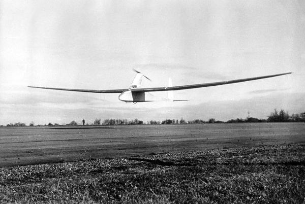
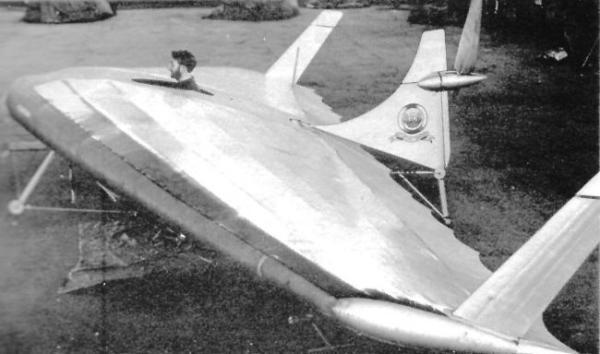
SUMPAC flying at Lasham circa 1961. RAeS collection
PLANFORM was based on flying at 10 feet (3 m) to comply with the rules of the figure-eight course. A span of 80 feet (24.4 m) was chosen. Their analysis showed that a larger span would require less power, but be more difficult to turn.
AEROFOIL SECTION
Aeronautical research had been more concerned with speeds of around the speed of sound than around the speed of a push-bike. The NACA 6 series aerofoils had been designed by the United States National Advisory Committee on Aeronautics, (now well known for its space exploits as NASA), for use at high subsonic speeds, i.e. speeds just below the speed of sound. In tunnel tests at high Reynolds numbers (see Glossary), it had been shown that over a large part of the area on these sections the flow was laminar. The group extrapolated beyond the tested range to a section of high camber, 653818. The 6 signifies the series, the 5 is a measure of the position of maximum thickness and the pressure distribution, (633818 is thickest further forward), the 8 is a measure of the camber (compare with Jupiter, Toucan and Linnet sections), the 18 signifies a thickness of 18% of the chord.( Today, aerofoil sections specifically designed for HPA are available. (Even computer programs on which you can tailor your own.)
TEST-SECTION
To prove the method of construction a test-section of wing was made. This had a "span" of 7 feet, to suit the wind-tunnel, and a chord of 3 feet, being the average of the expected chord on the plane. All construction was done as if it were to be part of the actual aeroplane. The primary structure was a spruce girder box-spar (two spars linked with other structure to form a box shape). All the spruce was bought in with a thickness of 1/8th inch. The four spar booms which formed the corners of the box were laminated from 1 inch by 1/8th inch strips, some of the laminations being Balsa. At the transport joints, the duralumin fittings, also 1/8th inch thick were bonded between laminations. The strips making up the vertical sides of the box were similarly incorporated. The two spars so built were then supported at the required twist and the remainder of the structure added. More spruce strips completed the top and bottom of the box-spar. Ribs were of girder construction with spruce booms and spaced at 9 inches. A true profile near the nose was maintained with a closer spacing in this area. The front 20% of this structure was skinned with 1/16th inch thick Balsa, and Balsa caps were added to the ribs. The trailing edge was spruce.
The details of this construction principle were arrived at from experience with the test-section, which exhibited laminar-flow on tunnel tests, and proved structurally sound when loaded. When loaded beyond the expected flight-loads, failure first occurred in the transport-joint fitting, not in the bonding of this to the spruce. The wing was covered with doped parachute nylon.
TUNNEL TESTS Three tests were conducted. The wing-test-specimen, the propeller, and a model of the aircraft. The wing-test-specimen displayed laminar-flow satisfactorily. The propeller, which had adjustable tips, performed as expected.
INTERFERENCE DRAG
However the drag of the model was excessive. It was discovered that this extra drag was being caused at the junction between the wing and the pylon. According to these wind-tunnel observations, this interference drag accounted for 2 (0.9 Kg) out of a total of 7 pounds (3.2 Kg). With a bluff section, such as a cylinder or sphere, the flow can be expected to separate somewhere on the downstream half of the section. In this region, as one proceeds in the direction of the flow, the cross section is decreasing. To avoid separation a gradual taper is needed as on aerofoils. If two aerofoils are adjacent at right angles to each other, as a conventional fin and tailplane, or as the SUMPAC wing and pylon, then the tendency for separation to occur is augmented. The pylon was thick enough for the pilot's head, the wing section was thick and their regions of decreasing thickness were adjacent. Separation was observed to be occurring on the tunnel-model at this place. The shape was adjusted to reduce this effect. This could not be done in an ideal manner because building was too far advanced and such a fairing would have been within the sweep of the propeller blades.
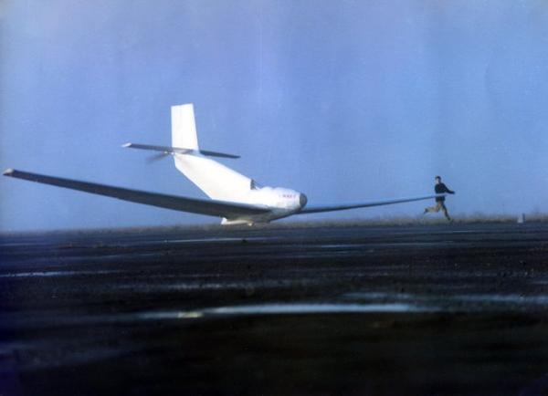
Construction started in January 1961. The group were awarded a grant from the RAeSMPAG in February. The plane was transported to Lasham, an airfield in Southern England greatly used by sailplanes, in September. Derek Piggot was the Chief Flying Instructor at Lasham, and became SUMPAC test-pilot. The first flight was on November 9th. Even with his experience he reported that landing was more difficult than taking off.
AIRFRAME PROBLEMS
The dampness of the hangar warped the nose-skinning and slackened the nylon. This meant that extra coats of cellulose dope were added to try to maintain tautness. The tubular framework supporting the pedals and nosewheel collapsed on early ground runs and was replaced with a light-alloy-sheet structure. The original fin was replaced with one of twice the area. The steel transmission belt slipped and stretched.
FLYING On SUMPAC,
The gear-ratio between the wheel and the propeller was adjusted before each flight to suit the anticipated wind-speed, but even so the pilot often found that the wheel was slipping. When speed has increased to the stage that the weight of the plane is nearly all carried by the wings then there will be very little grip because the pressure on the wheel has been lifted. On SUMPAC when the wheel slipped it then became essential to continue to accelerate to full take-off speed, thrust coming from the propeller. Early flights were made at too steep an attitude (i.e. the nose was too high) until Piggot became accustomed to the controls and to the plane. The longest flight was 650 yards (594 m). Turns were attempted, with 80 degrees the best achieved. SUMPAC made a total of 40 flights. Some of the later flights were under tow or with the assistance of a model-aeroplane engine. Instrumentation was a Cosim variometer.
ALAN LASSIERE at IMPERIAL COLLEGE ,the LONDON GROUP
At the beginning of 1963 after 14 months at Lasham, Alan, one of the original three, took the plane to Imperial College to develop it to a hopefully improved performance. The wing was left untouched, the fuselage was virtually rebuilt. The new transmission was by fabric belt, the new forward structure all of light-alloy sheet. The pylon was reshaped to avoid the separation mentioned above. The fuselage was covered with Melinex, (see Glossary). These modifications took twice as long as the original designing and building. SUMPAC was taken to West Malling in 1965. Unfortunately before any improvement in performance could be noticed, a flight on 12th November 1965 ended in disaster. John Pratt, chosen for his cycling ability was aboard. Having flown fifty yards, Pratt found himself at 30 feet (9 m) in a stalled aeroplane, perhaps due to a gust. One wing hit the ground first, breaking it; then the fuselage hit, causing further damage. John Pratt was not injured, but the airframe was considered beyond repair. SUMPAC then became the first HPA to be displayed at the Shuttleworth Collection of historic aircraft. Alan, since then, has created a monumental archive on the subject of HPF.
PUFFIN
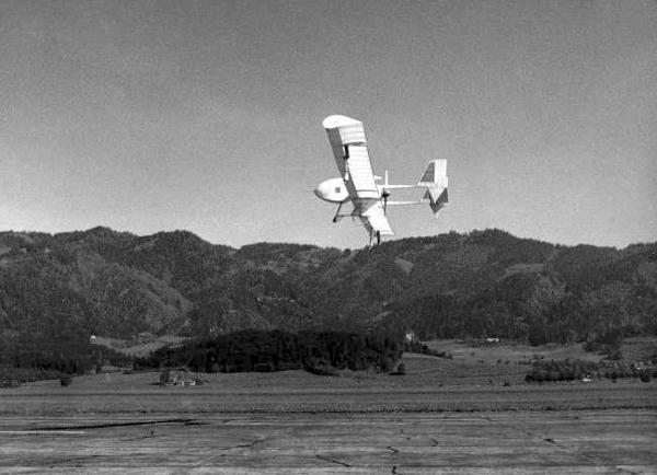
Within a week of SUMPAC's first take-off, there were two HPA flying in England. Puffin first flew on 16th Nov 1961. The report in "Flight", of this event concluded " .. an attempt on the Kremer Prize appears to be imminent". This is what was generally believed: at the time the words appeared superfluous and self-evident, but 16 years were to pass before the figure-eight was flown. Hatfield, within 80 miles (130 Km) of Southampton, was the home of the De Havilland Aircraft Company Ltd. Frank Vann, structural engineer, John Wimpenny, aerodynamicist and other employees of this company trod a path remarkably similar to that of the Southampton graduates described above. With the approval of Geoffrey de Havilland the Hatfield Man-Powered Aircraft Club was formed. Care and attention went into the design and construction of Puffin as would be expected from people in the aircraft industry.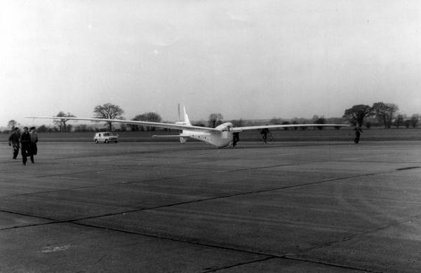
Puffin 1 at Hatfield circa 1961. RAeS collection
SIMILARITIES between Puffin I and SUMPAC :-
No unproved aerodynamic concepts, such as flapping wings. Both:- Single-seat monoplane. Bicycle-style pedals. 9 ft (2.75 m) diameter propeller. Main material, wood. Driven bicycle-type ground wheel. Conventional control surfaces, operated by bicycle-handlebar-type pilot's control. Control system linkage by lightweight cable
|
Dimensions |
Span ft (m) |
Area Sq ft (m2) |
Weight lb (Kg) |
|---|---|---|---|
|
Puffin I |
84 (25.6) |
330 (30.7) |
118 (53.5) |
|
SUMPAC |
80 (24.4) |
300 (27.9) |
128 (58.1) |
DIFFERENCES between Puffin I and SUMPAC :-
On Puffin, pilot position upright. propeller behind tail. Transmission by bevel-gear and shaft. Stressed-skin wing-structure. Group members were workers in the aircraft industry. Approached the design of their HPA with an experienced and sophisticated attitude. This Hatfield group had support from the firm, including dry hangarage. Members lived in or close to Hatfield, where the plane was built and flown. On SUMPAC, pilot position recumbent. propeller on pylon. Transmission by steel belt. Box-girder wing-structure. Group members were graduates and undergraduates. A thorough theoretical optimisation was conducted before finalising design, but this was the first aeroplane by the designers. Simple effective techniques were used. The group had the use of a University laboratory for building, a heated space with a firm flat floor. But at Lasham, conditions were not so comfortable, and the airfield was at a distance from members homes. Both groups had input from the knowledge and ideas assembled and disseminated by the RAeSMPAG.
In 2007, the relative merits of upright and recumbent are still debated, as are propeller positions, transmission systems and lateral control systems. Since the advent of composites, structures are very different, although some of the same materials are used. More attention is paid to interference drag at the outset.
PUFFIN CONFIGURATION
John Wimpenny said "We didn't make the fuselage that fancy shape for the sake if it, but in order to accomodate the transmission tube". See above (Mufli) where the effects of propeller position are discussed. This layout also led to a very short aeroplane, (see also Linnet). A single-crew layout was chosen "to reduce the work required in the very arduous task of producing an aircraft of this nature."
TESTS
A wing test-section was mounted on legs in the open air. On a day when the wind-strength was appropriate, the flow over this section was investigated. It was felt that this would avoid the turbulence associated with wind-tunnels or the vibration associated with car-roof mounted models. Structural tests on the wing test-section suggested increasing the size of the internal vertical struts. A transmission rig was useful in demonstrating the efficiency of the drive and for checking prospective pilots' power output. A fuselage structural test-piece was made; a few feet of typical proposed rear-fuselage at full-scale. This proved the integrity of monocoque Balsa design, (see monocoque in Glossary). The pilot-support structure was a magnesium tube framework. Wing root (centre) aerofoil for Puffin I was a Wortmann section modified by making the bottom flat. Tip section was a NACA 4 figure section.
CONSTRUCTION
All of the fuselage and tail and most of the wing on Puffin I was Balsa wood. The sub-structure, the fuselage frames and wing ribs were all built of Balsa sheet or strip. Puffin I in flight is seen with a straight wing. The wing-spars were built with a pre-calculated downward curve such that they would become straight when loaded. These spars were then sprung into the wing-jigs which were straight. Then the Balsa skin was added. This meant that the skin was not stressed by the bending loads. This skin was a single thickness of 1/16th inch (1.6 mm) Balsa with the grain at 45 degrees to the span. Large panels were first assembled from the 4 inch (101.6 mm) width produced for model aircraft. Then this panel was glued onto the structure. This operation was done by as large a team of people as could get close enough to work at once, so that it could be accomplished before the glue went off. This resulted in an excessive weight of glue. Projected wing-weight estimate was 39.4 lb (17.9 Kg), but the actual wings weighed 63 lb (28.6 Kg). The completed wings were carried by hand a mile from the De Havilland Apprentice Training School to one of the main Hatfield hangars. Here everything was glued together. No way could Puffin I be transported. During the flying stage it was found that the Balsa skin had warped after a few months. The wing-surface profile was no longer smooth, and this was increasing the profile drag.
Now, the front cockpit canopy of Puffin was removable to let the pilot in. To make an airtight seal around this canopy, the group had used a few feet of "Cling". This is a proprietary draught excluder intended for the doors and windows of houses. It is a strip of sponge with adhesive on one side. It is lightweight and the obvious choice for this application, and this little detail is hardly worthy of mention except that it provided the solution to the wing-skin warping problem. Strips of this same rubbery foam, (quite different from the rigid foams used in later years for secondary structures), were stuck onto the outside of the existing wing (without removing anything) following the position of every rib, which were at 4 inch (101.6) pitch. The wing was then re-covered with Melinex above these strips. This provided a smooth surface, although not strictly the same aerofoil shape since it was now 3/16 inch (4.8 mm) bigger all round.
TRANSMISSION
The group sought advice from Dunlop Ltd with regard to a tyre for the aircraft. This firm responded by offering to make the whole wheel and the bevel-gear box, which was entirely satisfactory. The long shaft from the pedals to the propeller was originally made by laminating 1/64th (0.4 mm) Balsa around a mandrel. There was no method of adjusting the ratio of wheel to propeller revolutions, as there was on SUMPAC and later Jupiter. Effective tuning of this for take-off had to be done by adjusting the pitch of the propeller. Wheel-slip was encountered with Puffin but was no great embarrassment. Perhaps because of the lesser power-requirement of Puffin the technique of building up ground speed, holding some weight on the wheel, and then "popping up", was more easily done. On Puffin, the pilot was leaning further forward than a bicyclist, and was restrained by a harness. This was to relieve the hands of all weight, and arrange the centre of gravity correctly. With concentric wheel and pedals, similar to the author's 1960 design, the position of the feet is of course constrained. This imposes a restriction on positioning of the major items: wing, pilot, wheel. There would appear to be an implicit hazard in this arrangement of the pilot being thrown forward over the wheel in a bad landing. The layout was such that, statically, with the weight on the wheel, the aircraft would start to rock forward at an angle of 15 degrees from the horizontal. To surmount this, the Puffin group added a strut protruding forward for the purpose of absorbing impact in such an eventuality. (On Jupiter, the author positioned the main wheel well forward of the centre of gravity in order to avoid such a nose-over. However this had the disadvantage of too much weight on the tail-wheel.) (On Monarch, after a crash with the original layout of an upright pilot, the group rebuilt the fuselage with a recumbent position.)
The Puffin was built in just over a year by November 1961. It first rolled out on the evening of 15th of November when a book of birds was consulted to see which it most closely resembled. You can see a design on your drawing board, you can see the plane when it is being built, but you never see what it really looks like till you get it outside. A puffin it was. In contrast to the many days of ground-runs of SUMPAC, Puffin lifted off the next day, and it didn't require as much puffin' as its contemporary. A horizon reference bar was mounted well in front of the nose and this proved excellent, particularly when the other instruments were also mounted here so the pilot only needed to look in one place. John Wimpenny found that it was better to maintain constant speed than try to maintain constant attitude.
FLIGHT TESTS
included drag measurements by towing via a spring balance. The pilot found this adversely affected stability and spring-balance-towing was terminated as soon as the measurements had been obtained. Drag was found to be 30% above estimate before the foam-rubber sponge as described above was added. In a further attempt to reduce drag, all control hinge-lines were sealed. A wheel brake was added and the mid-span skids removed. A pedal revolution meter was fitted linked to two coloured lights, red and green. A shining red light meant "pedal faster". It was 39 year-old John Wimpenny, one of the initiators and designers who did most of the flying and who exceeded the 779 yards (712 m) of Mufli with a straight line flight of 993 yards (908 m) which was well independently observed since delegates to an IATA conference happened to be at de Havilland's at the time. The photograph of Wimpenny in the plane with the front fairing removed and a big smile on his face was on the cover of the next day's tabloids with headline "Puff, Puff, Puffin !". It was presumably assumed that their readers could sometimes cope with words of two syllables, but not with the names of two people. Understandably, others in the group wondered why it was only J.W. who was mentioned.
Sustained turns, however remained elusive, since, as for SUMPAC, pilot effort had to be directed mostly towards turning the pedals. With either remote-control or an engine, the pilot would only have to concentrate on either controlling or pedalling. As with SUMPAC, the Puffin group added a model-aeroplane engine, and turns up to 270 degrees were flown. Angle of bank was between 5 and 10 degrees. The group were able to make a demonstration flight for the benefit of the spouses and relatives of group members as some recompense for the many hours that the members had been away from them and with the project.
PUFFIN II
With a cyclist at the controls in April 1963, Puffin I crashed. The entire wing and fuselage were destroyed. Using the salvaged propeller and gearbox, the plane was redesigned to a span of 93 feet (28.3 m) and an area of 390 sq ft (36.2 m2). Dr Wortmann sent the group a selection of his aerofoil section ordinates and test-results. All these had been specifically designed for HPA. The group selected FX63137. This section, although giving good ratios of lift to drag at the speeds and incidences encountered by HPA, produces a high lift moment (see below for comments on this aerofoil section by John Potter and others ). On the ribs for the new wing, allowance was made for the thickness of sponge strips as added to the first plane. Much attention was paid to getting a good surface. The fuselage was almost identical, but the wing structure was now a box-girder, with spruce for the booms and Balsa for the top and bottom diagonals. The rib-pitch of 4 inches (101.4 mm) was retained. The empty weight was 140 lb (63.5 Kg). The first flight of Puffin II was on 27th Aug 1965. Results were not as good as had been hoped. Little more was achieved in turns, and none in distance. A wide variety of ingenious lateral control devices was tried. A pair of spoilers was added at each wing-tip (4 in all). These would be opened on one side only to pull that wing back. The Puffin II had differential ailerons, as commonly used on gliders, where the up-moving aileron usually travels more than the down-going. A range of ratios was tried on Puffin II. with deflections up to 70 degrees up and 10 degrees down.
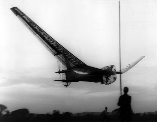
Puffin II flying at Hatfield. RAeS Collection
HINDSIGHT
Commenting, in 1989, on the lack of improvement, Wimpenny, now Professor J.Wimpenny attributed the disappointing performance of the Mk II partly to the fact that the increase in wingspan without additional tail area led to directional control difficulties. Control, he says must always be resolved first, before trying for duration. (An engineer, not an operator speaking.) Any of today's home-computers will show that the ordinate points on FX63137 do not lie in a smooth curve. In 1989, Prof. M. Drela, using his advanced aerofoil design program (see Daedalus), found that the section produced more drag than the early wind-tunnel tests would indicate. On hearing of this, Wimpenny considered that this also would help to explain the disappointing performance. In the author's opinion, if Puffin II had not suffered from this handicap, perhaps by using a different section, then it would have easily outperformed his own Jupiter, and this would have influenced the design of those machines which followed, such as Stork, since they might have tended to follow Puffin.
Prof. Wimpenny continues, 2007, to promote HPF, and with his son Gerard and the author and others co-laborated on a human powered flight simulator.
LIVERPUFFIN
The Puffin II hit a concrete runway-light post in April 1969 and the group at Hatfield handed over all the remains to Dr K Sherwin of Liverpool University. The wing structure was mendable, and the transmission and propeller were salvageable. Sherwin's approach was not to aim for the Kremer prize or for record distances, but instead to work towards a type of HPA which could be flown on days that were not absolutely flat calm, and for a simpler less expensive machine that could nevertheless leave the ground. Lippisch, mentioned above, agreed in the 1960s with this view. New, outside Japan, (see Linnet), was the idea of a student project initiated and led by the University staff..
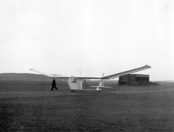
Liverpuffin in 1972. RAeS collection
STAFF LED UNIVERSITY PROJECTS
The difficulties which are met when trying to encourage undergraduates to work creatively and as a team are discussed by Sherwin (1976) :- "On their own the students were quite happy to discuss these [agreed] findings in general terms but were not prepared to use them as a basis for decisions regarding [design].."
and -
"It was difficult ... to persuade students to make the transition from innovation to detail. All too often...students would come forward with an idea but without any details or anything written. When told to quantify their idea they would go away only to change the idea for something `better' and later present this, again without anything on paper." And on the subject of take-overs after discussions with John Potter and Frederick To :- "Unless one is offered a complete man-powered aircraft that requires only a small amount of repair work before it can be flown, it is much better to start such a project from scratch, particularly in view of the enthusiasm that should be generated by a complete project". The same wing section was built up again on top of the salvaged spar using hot-wire-cut polystyrene. Solid blocks were obtained large enough to form the nose of the wing. The outside profile was cut, then most of the middle cut away. This avoids the labour of many ribs and the difficulty of forming a sheet material around the nose accurately. Thus Sherwin pioneered the system later used on Light Eagle and Daedalus. Sherwin then cut circular holes in these nose-forms, an arguably bad move, because accuracy of shape was lost. This was the first HPA to fly with a pod and tail-boom. The original Puffin propeller was mounted behind the pod, with thus a much shorter transmission. Control was by rudder only. Span, in the spirit of Sherwin's endeavour for a simple plane was cut to 64 feet (19.5 m) which gave an area of 305 sq feet (28.3 m2). The weight of LiverPuffin was 140 lbs (63.5 Kg). First flight was on the 18th of March 1972. No long flights are recorded.
SINGAPORE
Later Sherwin joined the staff of a University in Singapore and with the benefit of his Liverpool experience persevered with the idea of student projects. The year-batch was split into two groups, with the idea that each build an HPA. Some raw materials were provided. One of the aeroplanes flew and the other did not.
McAVOY
If the rules for a competition stated that the HPA must have a three wheeled undercarriage, the span must be not more than 54 feet (16.5 m), the pilot must be unfaired, the tail unit must be an annulus surrounding the propeller which must have four blades, then entrants might well produce machines very much like that of James M.McAvoy of Georgia Tech. Otherwise, why attempt so many innovations on one design ? McAvoy's wing area was 289 sq ft (26.8 m2) and the weight was no more than 126 lb (57 Kg), typical of the areas and weights of contemporary successful machines. He had used an aluminium and Balsa structure and the drive was by bevel gears and a shaft. McAvoy was an aeronautical engineering student and it would appear that his design was sound. Unfortunately there was no opportunity to tell how many of his novel features would have worked, because the machine rolled over when 50 yards (45 m) into its first attempted take-off run and the damage was severe enough as to preclude further attempts.
VINE
S.W.Vine of Krugersdorp, Transvaal, South Africa was an expert glider pilot who also had engineering experience. His HPA had a layout similar to that of a single seater engined aircraft. The propeller, small by HPA standards, was driven by both hands and feet. The wing section is quoted (Reay 1977) as a modified Gottingen 535 but photographs indicate a slimmer section. Weight was 205 lbs (93 Kg) with a wingspan of 40 feet (12.2 m) and an area of 220 sq.ft (20.4 m2).
POLITICS & the SPORT of HPF
The Kremer figure-eight competition was at this time open to citizens of the British Commonwealth only. When Vine started building his plane in 1961 he was just such a citizen, but it had been decided by the powers that be in his country that on 31st May 1962, South Africa would quit from the British Commonwealth. On the 17th May, with a fortnight of political eligibility remaining, the plane was complete, but the weather highly unsuitable, being windy and gusty. Vine decided to have a go. Accounts of the flight remind the author of one of the flights of Jupiter ten years later: take-off into the stiff breeze: satisfactory straight flight for several hundred yards: gust lifts plane: pilot loses control: plane crashes. Mr Vine, although 70 years old, survived uninjured. Unfortunately the aircraft was destroyed, and this was its first and last flight. Presumably otherwise he could have transported it the 150 miles from Randfontein into neighbouring Botswana, then Bechuanaland, to regain Kremer eligibility.
RELUCTANT PHOENIX
Daniel Perkins, who had built several inflatable HPA which had not flown, (see above), met with success with his design of the Reluctant Phoenix, the first inflatable to fly. This plane was designed to fly very low, so that the height was a fraction of the chord of the wing, (see ground-effect in Glossary). Perkins had made some tests, and found a symetrical aerofoil to be appropriate. To quote Frederick To (Aerospace June/July 1985) and (Society of Automotive Engineers Inc) :- "The aircraft was a delta flying-wing with a wingspan of 31 feet (9.5 m) and an empty weight of 39 lb (17.7 Kg). The envelope of the wing was made of polyurethane-coated nylon fabric. Due to the high power requirement for cruise, the aircraft was limited to short hops under man-power as it was being flight tested inside an 800 ft (244 m) long airship hangar. About 90 flights were made. Reluctant Phoenix was successful in that it could be folded away and transported in the back of a small station wagon. It also survived many crashes without requiring repairs as the aircraft merely bounced when in collision with the ground. Shortly after Perkins's death the Reluctant Phoenix was handed over [to Frederick To], who immediately recognised the advantages of the system". This author visited Fred To and heard him praise the neatness of the design of the Reluctant Phoenix. The seat-frame was similar to the chassis of a recumbent road HPV, the pilot's control bar being below the knees. See Phoenix.
Reluctant Phoenix
THE EARLY NIHON AIRCRAFT LINNET I, II, III, and IV
This series of early successful aircraft were all student projects built at the The Research Institute of Science and Technology, Nihon University, Japan, under the leadership of Professor Hidemasa Kimura. The project was ".. conceived in 1961 soon after the news of Britain's SUMPAC and Puffin
were received. April 1963 marked the beginning of the first year of research," which entailed "A device to measure the power generated "; a propeller driven trolley was built at Nihon, to prove the possibility of take-off without wheel-drive. "The second year was devoted to operations research to determine the optimum airframe dimensions, weight, aerodynamic characteristics and other factors to make flight possible. The basic form of the airframe was defined on the basis of the research. The third year marked a transition to detail design and manufacturing. The long-awaited airplane was rolled out in February 1966. "On 25th February 1966, our dear Linnet, with Munetaka Okamiya at the controls, lifted wheels off ground for the first time.... "Because of his aerial feat, Mr Okamiya became the first Japanese who was able to walk on the ground, swim at sea and fly in the air using his own power" (Kimura 1977). But Okamiya had not needed a machine which had taken three years of research by a University Institute of Science and Technology in order to do his walking or his swimming. Human powered flight has only been made a reality by engineering. But human powered flight is not the same as engineering. The Linnet I is in the author's opinion the best looking HPA ever built, but as Kimura's remark implies, its purpose is to enable flight, not just to look pretty. Linnet I was the first HPA to fly without having to carry the weight of a wheel drive in the air, but the longest flight was only 47 yards (43 m). Transmission on the Linnet series was by bevel gear and shaft (see Mufli for a discussion of transmission and pitch control of Linnet ).The single wing spar was spruce, the ribs Balsa . This framework was covered with styrene-paper, about which Kimura enthuses :-
".. a thin sheet made by rolling styrol-resins at a thickness of about 0.5 mm [0.02 inch ]. Such material is light and effective in enhancing the rigidity of the airframe. It is also smooth in outer surface finish, a quality which is far superior to that of Britain's Melinex whose surface is slackened like a wet paper screen .. "
Achieving an accurate profile shape without excessive weight is indeed one of the key points on an HPA. Kimura's criticism of polyester film is particularly valid when applied to areas of high curvature or double
curvature. Looking at the fuselage-pods of many HPA one can see that the shape has been determined by the designer's knowledge at the outset that it would be made of polyester film supported by a framework. This constraint did not apply to the Linnet fuselages which helps to account for their elegant appearance and reasonably accurate profiles. On the wing, the styrene paper covering was apparently alone in providing any torsional rigidity. Kimura again :-
"...subsequent models continued at a pace of one airplane every year except for the period during which the University was embroiled in faculty-students disputes. " Data for all the Linnets are shown in the table. For subsequent activity at Nihon see Egret.
Linnet 1 flying in 1966. RAeS collection
MALLIGA
Polystyrene sheet was a material also much used by Josef Malliga, but here the similarity with the Linnet series ends. In 1967 Josef Malliga was a pilot in the Austrian Air Force. This man designed the Malliga and built it on his own. Even the aerofoil section was his own design. Wing spar was aluminium tube with ribs and skin of expanded polystyrene foam (EPS). The ribs were capped with plywood strips. The pilot's feet are at the same height as the propeller hub, which is just behind the pod, and transmission is via bevel gears at the pedals, and a shaft straight back to the propeller. This layout necessitates a tall undercarriage. The wheel was not driven. (Tony Paxton of England made a machine of similar layout, but the Paxton machine made no flights.) Wing span was originally 65 ft (19.8 m) with a weight of 113 lb(51.2 Kg). After some towed flights, the first pilot-powered flights were in the autumn of 1967 with distances of up to 150 yards (137 m). To improve performance the span was increased to 85 ft (26 m) and the propeller diameter increased from 6 1/2 ft (2 m) to 9 ft (2.75m). This led to flights of up to 380 yards (350 m)
.
Malliga in it’s original form airborne. RAeS collection
PROPELLER EFFICIENCY
Josef Malliga's increase in propeller diameter will have helped because efficiency increases with diameter.
Propeller efficiency is usually quoted as a percentage; (90% is a figure that might be assumed for a good HPA propeller). What this means in physical reality is that 10% of the energy arriving at the propeller hub is being wasted on pushing the air backwards, spinning it around and in creating turbulence in the wake.. The other 90% of the energy is pushing the aircraft forward. It is perhaps easiest initially to think in terms of trying to reduce the inefficiency, that is to reduce the energy loss.
The thrust produced must at least equal the drag of the aircraft. One cause of energy loss is due to the momentum of the air pushed backwards. Knowing the values of diameter, speed and thrust one can quantify this. This is present even if the propeller is perfect in all other respects. Its only imperfection, hypothetically, is that it does not have infinite diameter. The efficiency so calculated is known as the `ideal efficiency'.
The propeller with ideal efficiency will have an ideal distribution of thrust along the blade. In practice this will not be the case.
Here is a simplified approximate method of calculating propeller efficiency. This is for first estimates only. K is a factor to allow for non-ideal thrust distribution. K has been found to be of the order of 2.
Given Diameter D ft, Velocity V ft/sec and thrust T lbs,
Induced loss = K x ( 188 x T )/( V2 x D2 )
Using this to estimate the improvement on the Malliga due to propeller diameter change alone, making the same assumptions about thrust and velocity for both diameters. The length of flights achieved indicate that the power required was of the order of 0.5 HP or 275 ft lb/sec Let us assume a velocity of 20mph or 30 ft/sec. This is based on known flying speeds of other HPA of similar wing areas.
Since Power = Drag x Velocity , drag = 275/30 = 9 lb
Hence thrust = 9 lb
With D = 6.5 , V = 30 , T = 9
induced loss = 2 x ( 188 x 9 )/( 30 x 30 x 6.5 x 6.5 )
= 0.08 = 8 %
With D = 9.0 , V = 30 , T = 9
induced loss = 2 x ( 188 x 9 )/( 30 x 30 x 9.0 x 9.0 )
= 0.04 = 4 %
an efficiency increase of 4%
therefore 4% less power is needed
Four percent may not seem like very much, but it is only by saving a few percent wherever one can that flight becomes possible or flights become longer.
The factor K will effectively be reduced with a "minimum induced-loss" propeller. It will never be less then one. K=1 is "ideal efficiency".
In the above case, actual propeller efficiency will be less than 96% because of the energy lost by the drag of the blades, and other losses. See (Sherwin 1971) for a method of blade element analysis or (Glauert 1948) for classical theory. Glauert`s theory however ignores the effect of the number of blades. Ernst Schoberl has plotted the propeller diameters required to provide 85% or 89% efficiency for a range of flying speeds (Schoberl 1987). These plots were drawn in 1987, when HPA had developed to the point that less propeller thrust was required than at the time of the Malliga; they confirm that a diameter increase of the order of magnitude made by Josef Malliga provide an efficiency benefit of 4%. There are now , 2007, several computer programs which can be used to design a propeller. One is by Malcolm Whapshott and another that the author has used is Xfoil
VENTILATION
Ventilation is always a problem on HPAs. When the author's mother first saw the project drawing of Jupiter she asked "How is the poor chap going to breathe ? ". The author made the mistake of thinking this was nonsense, being more concerned with sealing every gap to reduce drag. In practice the "poor chap" was never short of oxygen, but the windscreen used to mist up, and we had to cut a direct vision hole. On wheel driven machines there is inevitably a leak source around the wheel as on many road HPVs. However, on all the early British machines, holes had to be cut to provide fresh air, the air leaking in around the wheel not being in the right place. Later HPAs show sophistication in the breathing tubes with the Daedalus being a good example; the inlet was carefully positioned and the duct shaped to minimise energy loss.
VENTILATION, COOLING & DE-MISTING METHODS have included :-
Double Glazing
Propietary de-mister
Vent Duct
Use of non-perspiring pilot during taxiing
Sun-shade above pilot
On the Malliga, ventilation was provided by the simple expedient of extending the fairing only to the pilot's shoulders, leaving the head in fresh air.
One could say that the weight-cost of ventilation-provision would be a credit. (Some flights on several HPAs have been made without the pilot's door).
SM-OX
see Table of types.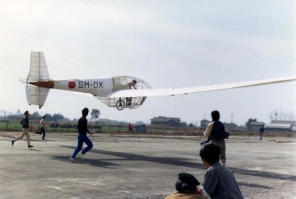
SM-OX flying circa 1969. RAeS collection
"MAN POWERED FLIGHT"
So titled, the first book on the subject, was written by Dr Keith Sherwin of the University of Liverpool, England, in 1971, (see Bibliography). Published by the publishers of "Aeromodeller". Ron Moulton, editor of this magazine, later served excellently as Chairman of the RAeSMPAG. A human powered aircraft is not a model aircraft any more than it is a glider or a bicycle. But we can benefit from the judicious application of some of the knowledge and experience of these other pursuits.
OTTAWA
Czerwinski developed a new method of strong lightweight construction for HPA (Czerwinski 1967). This uses a framework of aluminium tubes. The joints are made by lashing with glassfibre. This principle was used by the Dumbo/Mercury, and was a precursor to the use of lashed tubes of more modern materials, eg carbon, Kevlar. A two-seater aircraft with two propellers was designed using this constructional system. The author knows of no record of flight trials.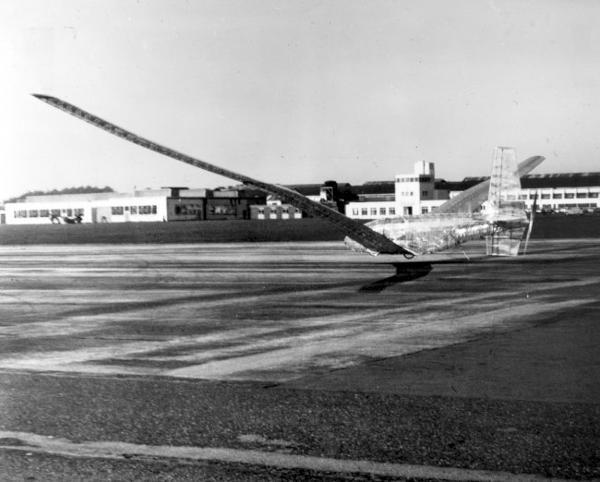
Dumbo flying at Weybridge circa 1971. RAeS collection
DUMBO/MERCURY
P.K. Green, W.F.Ball and M.J.Rudd were employed at BAC Weybridge, UK. This airfield is of interest, having been built on the famous Brooklands race-track, and was the home of the Vickers-Armstrong Aircraft Company, now part of British Aerospace. It is south of London, not far from Farnborough. The project started early in 1966. The aim of the designers was to increase wingspan without increasing weight. They considered that much of the weight on a wing is there only as structure to resist the loads, particularly torsional loads which occur when ailerons are used. They estimated that by eliminating ailerons, a 120 ft (36.6) m) wing could be built for the same weight as the 80 ft (24.4 m) wings of SUMPAC or Puffin. For lateral control the whole wing twisted from the root.
In 1967 they learnt of the Czerwinski method of joining light alloy tubes as developed by the Ottawa group (JRAeS Jan 1967) and decided on this method of construction. Test-pieces of wing-spar (but without the enveloping secondary structure), the proposed transmission system and the innovatory wing-hinges were tested with practical help from the company. These hinges were not the simple affairs of the Mufli because this was a fully cantilevered wing. A recumbent pilot position was chosen, and a tail mounted propeller. With a shaft to the propeller, the rear part of the plane was like a neater version of the Puffin, having all moving surfaces.
Construction started in mid 1968. As for Puffin 1, the wing spar was built curved so that it would straighten out in flight. The spar and the fuselage frame were girder-principle, built up from light alloy tubes etch-milled down to a thickness of 0.010 inch (1/4mm). The etch-milling was done by the company. Etch-milling involves chemicals of a strength which take it out of the realm of "kitchen-table" processes. However, using suitable precautions, later groups devised their own equipment. (See Gossamer Condor & Monarch).
The parts for the secondary structure were made in member's homes. Each elaborate built-up-Balsa-strip fuselage frame was quite a piece of work in itself, but the individual ideas of each member are apparent in these, as in the wing ribs. It appeared to the author when he viewed the machine that not as much loving-care had gone into the nose-skinning as had gone into the components. The wing was not a smooth shape and the associated high profile-drag must have offset the advantage of reduced induced drag from the enormous span.
Dumbo was originally covered in transparent Melinex; close scrutiny of the photograph in Sherwin's 1971 book (page 116) is needed to see that it was covered. The same photo is in Reay's book with caption "uncovered" !
When built, the centre of gravity was found to be further aft than required for stability. This meant that ballast had to be added, and it was at the nose that it was needed, so there was not much moment arm to help.
First flight, with Chris Lovell, cyclist and glider pilot in Dumbo's rather cramped cockpit was on 18th September 1971. The name "Dumbo" was a joke which stuck, because someone thought it looked like an elephant with big flapping ears because the wings were so flexible.
Performance of Dumbo was disappointing considering its wingspan, and there were only a few short flights at Weybridge, partly for lack of pilots. Dumbo was found to be directionally unstable.
The plane was taken over in April 1974 by John Potter who had gained experience restoring and flying Jupiter. He refurbished the wing and renamed the plane Mercury, but it did not perform much better than it had at Weybridge. First flight as Mercury was July 1974. Potter gives some tips for ground-handling and hangar-storage in his account (Potter 1975)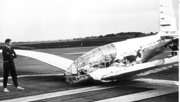
Flight LieutenantJohn Potter standing next to Mercury at RAF Cranwell in 1975
NORTHROP INSTITUTE of TECHNOLOGY Malcolm Smith of NIT, Los Angeles, USA, and reportedly 200 students were building a two-seater MPA in 1972. This would have had a wing of 78 ft (23.8) span and 288 sq ft (26.8 m2) area. Using a Mylar/Honeycomb sandwich they hoped for a very low wing weight and an accurate manifestation of a modified Wortmann section. Proposed crew were pilot Rose M. Licher and an athlete Scott Claypool.
MAYFLY
This unfortunately named machine was from the author's viewpoint, "the other Essex project", (Southend and Woodford being two towns in the English county of Essex, 40 miles (65 Km) along the Thames from each other). There were several other similarities with Jupiter. The wing foil section was identical (NACA 653618), and the wing structure was similar. On both projects, the building work took much longer than first estimated, there being several optimistically forecast completion dates which did not materialise. Beverley Shenstone used to visit and encourage both groups, sometimes on the same day. Neither project met with success while in Essex. The first Southend design incorporated a tubular wing-spar. This design was not awarded a RAeS grant. The first Woodford,Essex design incorporated a tubular tail-boom. In 1961 this was not awarded a grant either. The Melinex used on both machines was aluminised, rather than the more commonly used clear plastic.
The original Mayfly design was by Brian Kerry, an aerodynamicist working at the then Aviation Traders company. Kerry's design was in 1960, that is before any human had flown. This design was modified by other group members, and after comments from members of the RAeS MPAG committee. The front view of the fuselage was, in its final form, rectangular, to accomodate the two crew side-by-side. Wingspan was 90 feet (27.4 m) and area 405 sq.ft (37.6 m2).
Construction started in the summer of 1961 with completion estimated for May 1962. As it transpired the first attempted flight was in July 1965. The Mayfly did not fly, although some observers claim they saw light under the wheels on some runs.
Layout and control surfaces were as a glider. The propeller was on a pylon at the nose. The wing structure was a single spruce and ply spar, with a nose torsion box of 1/16th Balsa with the grain in line with the span, (cf Puffin I diagonal grain and Jupiter 2 ply diagonal Balsa skin). Drive to the propeller from the two recumbent crew was by twisted chain. Mayfly had a nosewheel, and the main wheel was driven.
With its silver covering, in Shenstone's words it "looks just like an aeroplane", and it had been built following the same principles as the other sixties British planes. Yet it did not take off, despite an airline pilot and racing cyclist sitting side-by-side and doing their best on ground runs.
Here are some possible reasons :-
The many modifications to the design of parts of the plane, such as widening of the cabin during the building, precluded a neat result.
The wing was warped, and there was insufficient spirit left after all that time to rebuild it, which is understandable considering the labour-intensive construction methods used at the time.
The transmission system involved 3 bearings in-line at the pedals with insufficiently rigid support.
Other problems included:-
Finding money for insurance premium:
Difficulty with rigging due to a redundant structure (too many points needed to line up at once and not all of them did):
cg not being where intended:
Difficulty for the crew to get in and out without damaging the fairing
Brian Kerry (1989 ) "We were all very young at the time and with hindsight, there are some things we would have done differently, but I believe that the two-seat concept is worth pursuing ". No help had come from the firm, and there were no experienced people frequently around, or anyone "keeping a fatherly eye", as he implied had been the case at Southampton (SUMPAC) and Hatfield (Puffin), although he agreed with the author that Beverley Shenstone had to a certain extent fulfilled this role.
As for group-structure he said that "we were not just a loose assembly of people but the group structure was a bit weak ". He spoke of the difficulties of keeping people motivated in a project which goes on for years. Much of the construction depended on voluntary help from local aero modellers putting in long hours. Towards the end, motivation dropped off, the team broke down and when the end wall of the Nissen hut at Southend, in which the derigged plane was stored, collapsed in 1967, causing damage to all three wing-sections, the heart of the group finally went out. However, Kerry considers that the fundamental design of the Mayfly was as sound as any of its contemporaries.
The propeller, designed by Brian Kerry and made by Martyn Pressnell was salvaged and used on Toucan.