
Jupiter
JUPITER
This if the author`s own plane, so here is an account of it from the first person.
SUMMARY of its history
1961 The "Hodgess Roper" design. I designed a tailboom-configuration HPA.This 1961 design is referred to by Lilley (April 1983), and elsewhere, as the "Hodgess Roper". This was never built. although I bought the tube for the tailboom, and some of this was used to make the pylon of Jupiter.
1962 The design was rethought and lessons learnt from accounts of SUMPAC and Puffin.
1963 "Jupiter" design. I designed Jupiter, and started to build it with the help of Susan Roper and others, calling ourselves the Woodford Essex Aircraft Group. We received a grant from the RAeS MPAG for the Jupiter-design project. At this stage it was referred to by some as the "Woodford".
1963-1968 Much of Jupiter was constructed at Woodford, Essex, by myself and others.
1968 I was prevented by ill-health from continuing.
1970 All the hardware was handed over to John Potter, ( then Flight Lieutenant J. Potter MA RAF ).
1970-1972 The project continued at Halton under Potter`s leadership, with the help of 99 others, including myself. completing the construction.
1972 Jupiter, my 1963 design, built at Woodford and Halton, first flew. All the best flights were in that year.
.Subjectively, my seven years of effort were well rewarded by being able to observe the excellent piloting of John Potter and others including Roger Hardy ( see Dragonfly).
OTHER REPORTS of JUPITER
Some histories of Man-powered Flight present inconsistent and even self-contradictory facts about this aircraft. This is understandable considering that the name changed from "Woodford" to "Jupiter", and I shortened my own name, ( at the same time as my brothers) from "Hodgess Roper" to "Roper". and Susan`s surname changed from "Jones" to "Hodgess Roper" when we married and then to "Roper".
From the bibliography, I recommend John Potter`s accounts of the flying aspects and the articles in Aeromodeller March to June 1973.
JUPITER TECHNICAL DATA
|
Wing |
Span |
79.6 feet 24.3 metres |
|
|
Area |
300 sq ft 27.9 m2 |
|
Aspect Ratio |
21.2 |
|
|
Root Chord |
5.59 ft 1.71 m |
|
|
Tip Chord |
2.23 ft 0.68 m |
|
|
Section |
NACA 653618 |
|
|
Dihedral |
5 degrees from 0.21 semi-span |
|
|
Aerodynamic Twist |
2 deg wash-in root to 0.21 semi-span 6.5 degrees wash-out 0.21 semi-span to tip 4.5 degrees wash-out overall |
|
|
Mean aero. chord |
4.03 ft 1.228 m |
|
|
|
|
|
|
Ailerons |
Type |
Plain |
|
|
Span (total) |
25.2 ft 7.7 m |
|
Area (total) |
24.2 sq ft 2.25 m2 |
|
|
Deflection |
Up 17 deg, down 17 deg (Alternative rigging, not used, up 45 deg down 0 deg ) |
|
|
|
|
|
|
Horz. Tail |
Type |
All moving |
|
|
Span |
15.0 ft 4.57 m |
|
Area |
27.5 sq ft 2.56 m2 |
|
|
Total travel |
36 deg |
|
|
Section |
NACA 63012 |
|
|
Tail Arm |
20.5 ft 6.25 m |
|
|
Aspect Ratio |
8.2 |
|
|
|
|
|
|
Vertical Tail |
Total Area |
24 sq ft 2.23 m2 |
|
|
Rudder |
11 sq ft 1.02 m2 |
|
Aspect Ratio |
1.4 |
|
|
Tail Arm |
21.5 ft 6.55 m |
|
|
Max Deflection |
30 degrees |
|
|
Section |
NACA 0012 - NACA 0006 |
|
|
|
|
|
|
Fuselage |
Max Width |
1.75 ft 0.533 m |
|
|
Overall Length |
29 ft 8.84 m |
|
Max Cross Section |
8.25 sq ft 0.766 m2 |
|
|
Undercarrriage Type |
Driven main wheel, non-castor tailwheel |
|
|
Wheel Diameter |
24 inch 610 mm front, 4 inch 101 mm tail |
|
|
|
|
|
|
Propeller |
Diameter |
9 ft 2.74 m |
|
|
Gear ratio pedal to prop |
adjustable on ground, 1.5, 1.7, 1.9(initially set at 1.7, 1.9 was favoured) |
|
Assumed pedal cadence |
72 |
|
|
Rotational Speed |
108, 120 or 137 |
|
|
Groundwheel gear |
69 inch 1.75 m(adjustable to 89 inches 2.26 m) |
|
|
|
|
|
|
Design Flight Envelope |
|
|
|
|
Max Load |
154 lb 69.8 Kg ( 170 lb, 77Kg was carried ) |
|
Max permissible AUW |
300 lb 136 Kg ( 315 lb, 143 was flown ) |
|
|
Design Manoeuvering Speed |
20 mph 8.9 m/s |
|
|
Design Diving Speed |
30 mph 13.4 m/s |
|
|
Ultimate Factor |
2.5g to -0.5g |
|
|
|
|
|
|
cg position intended |
25% to 31% m.a.c. |
|
|
measured 20 Nov 1971 |
|
|
|
|
150 lb pilot leaning forward |
27% m.a.c. |
|
150 lb pilot mid-position |
31% m.a.c. |
|
|
150 lb pilot leaning aft |
35% m.a.c. |
|
|
|
|
|
|
Weight of components |
March 1963 |
20 Nov 1971 |
|
|
original estimate lb (Kg) |
measured or derived lb (Kg) |
|
Wing |
67 (30.4) |
92 (41.7) |
|
Tail |
6 (2.7) |
8 (3.6) |
|
Forward Fuselage |
18 (8.2) |
15 (6.8) |
|
Rear Fuselage |
11 (5) |
14 (6.3) |
|
Propeller |
2 (0.9) |
3 (1.4) |
|
Transmission |
12 (5.4) |
14 (6.3) |
|
Total Empty |
116 (52.6) |
146 (66.2) |
NON-EXPERIMENTAL
Was Jupiter an experimental aircraft ?
An experimental aircraft :-
is of novel design,
does not get delivered to an operating organisation
is used for experiments
is usually modified during its flight test period
Out of these four, Jupiter scores about half a point, thereby contrasting strongly with most HPAs.
Design.
Very few innovations. Similar to its immediate predecessors in many respects.
Delivery.
During its design stage and all of the construction stage which required assembly jigs, Jupiter was under the control of an engineer. During its flying stage it was under the control of, and at the base of, an operating organisation, the Royal Air Force. The relevance of this "delivery" lies in differing learnt attitudes of the two people. As an engineer, I was used to thinking of an aircraft as something that one designed and built. John Potter, an RAF pilot, who had also flown with the Cambridge University Air Squadron was accustomed to climbing into aeroplanes and flying them.
Experiments
John Potter achieved a very hign usage of the plane, unusual in the sixties and seventies. he also fine-tuned the "engine", doing much cycle-training, Although he found himself at the helm of an overweight aeroplane of mediocre design, he concentrated on achieveing longer flights and was thus able to claim the World Distance Record. Those responsible for other HPA. such as Puffin 2, made many changes to the lateral control system and concentrated on trying to make the plane turn. With Jupiter it was not so much "let`s change this and see if it makes it fly better", as, "let`s pedal harder this time".
Modifications
Jupiter flew without needing any alterations, straight from the drawing board. The only modifications made after the first flight were the addition of a chain tensioner and of instrumentation.
Thus it can be claimed that Jupiter was the first non-experimental HPA. What was certainly true was the benefit to be gained by having a person of one background leading during the construction stage, and a person of a different background leading during flying.
THE AUTHOR'S SUBJECTIVE ACCOUNT of JUPITER
MY EARLIER YEARS :-
" One of the first things I was taught at school was that I had spelt my surname wrong. To prove teacher wrong took twenty-four hours. I took my birth-certificate to school the next day to show that I had spelt it right. "Another thing I was taught at school was that in order to fly by your own power you would need arm muscles six feet (two metres) thick. To prove teacher wrong in this instance took twenty-seven years and the help of a lot of other people.
MOTIVATION
I have always been interested in off-beat vehicles. In 1947, when I was 10 years old, I made what was effectively a skateboard. Unfortunately this was hampered by a fifth wheel in front for steering, and was much too long.
Later, when cycling down and up the valleys of Berkshire in my early teens, it often occurred to me, when about to descend a hill, how good it would be to be able to cut across in a straight line through the air to the top of the next hill.
PREVIOUS EXPERIENCE
I was an aircraft engineering apprentice from 1953 to 1958, and a design draughtsman until 1961, thereby gaining experience in many departments of aircraft-manufacturing firms, both in the technical offices concerned with design of airframes (not engines) and in workshops. With the possibility of sometime building an HPA in mind even then, I wanted to get experience in one of the offices concerned with production (analogous to the builder, rather than the architect, of a house. Quantity production is not necessarily implied; the `production' departments are busy on prototypes as well). However it was generally considered necessary for an apprentice to be versed either in design or in production, but not both, so I never worked in a production office. My main hobby was building canoes and then paddling them. These were all made with a spruce framework onto which was stretched a canvas skin. ("Fibreglass" was being used by others for some sailing dinghies). In one of these canoes I travelled down the Thames from home, and then around the coast and across to France, camping overnight on the way
1950s
The 1950s in Britain were a time of expansion. The Festival of Britain in 1951 showed that the nation had got its breath back after the war. For the first time ever there was a `youth culture' exemplified by rock-and-roll, and there was the money to buy gramophone records, teddy-boy clothes and motor-bikes. The power of youth was increasing and in 1958, as conscription for two years of `National Service' ( the draft ) ended, many males suddenly discovered that they had two years of unexpected freedom.
1959
In 1959 I was feeling that I would like to attempt something more original than another canoe and was wondering whether to build a human-powered submarine or a human-powered aircraft, and had started calculations and sketches for the former. Nobody offered a prize for a human-powered submarine in 1959, but I can remember being at home in my parents' suburban house where I lived, one lunchtime that November, and turned on the wireless to hear, as the valves warmed up, `...businessman has offered a prize of five thousand pounds for the first man powered flight. Our next broadcast .... '. I wasn't interested in their next broadcast, and suddenly I wasn't interested in submarines either. I reached for my slide-rule and started to calculate how much wing area would be needed. At this time I was more ignorant about what an HPA would look like than anyone reading this, although within a few months I began to get to hear of Mufli and Pedaliante through the RAeSMPAG. The details of the first Kremer Prize were not published for two months. I made a mistake that was consistently made by many people for several years, namely to suppose that anything that could fly would be able to get round the figure-eight course. I was a 22-year-old with no tools but those I built canoes with, and those I shaved with. I did have a Higher National Certificate in Aeronautics, and I was full of optimism. I even convinced myself that my ignorance on the subject of engines was almost an advantage on a plane that would not have one! Muscle-powered-flight had never been accomplished and maybe it would never be, but if anyone was going to, it might as well be me.
1960
There was another big event in my life in 1959. I met Susan Jones, later to become Susan Roper. This was three weeks after the Kremer announcement. Before long I had to tell her `Look, I am building an aeroplane', `I will help' she replied. I was 22, she was 19; we thought it would take two years. As it transpired she devoted eight years of her life to me and to the project. We married in 1963.
INITIAL DECISIONS
It never occurred to me that any type of aircraft other than a monoplane would be the appropriate layout. A cycling attitude for the pilot was chosen because it would require no experimentation. Bicycles work. You can take a dynamo drive off the wheel ( for the lights). I would take the propeller drive off in a similar way. However, there was no point in the weight of two big bike wheels and centre-of-gravity calculations of my first sketches showed the ( single) wheel position to be interfering with where the pilot's feet should be.
To make the pedals and wheel concentric as in the "penny-farthing" bicycles seemed to solve this, and my 1960 design had this feature. This dictates a minimum wheel size for the feet to clear the fairing (see fairing in Glossary) and the fairing to clear the ground. During various re-thinks, this layout for the front end remained
. My brother Geoffrey and I conducted some tests bicycling up and down a hill to determine power-output and air-resistance of the unfaired cyclist. The strengths of a few wood/glue/wood joints were tested. My job at this time was design draughtsman for metal aeroplanes. I needed to fill out the gaps in what I would need to know. At about this time,(early 1960), I visited The Cycle Show, an annual event in London, to see if there was anything which might be relevant. On one of the trade stalls were displayed a number of samples of chain. `Do you have a chain that twists ?', I asked. `Our chains do not twist' was the emphatic reply of the salesman. I then took hold of one end of the yard long sample of 8mm pitch chain with my right hand and of the other end with my left hand - and twisted - easily. I looked at the salesman. `Our chains do not twist' he repeated in exactly the same tone of voice. The drive chain for Jupiter was therefore acquired through a stockist, rather than direct from the manufacturer. This chain is about a third the weight of bicycle chain. For test, I made, by hand, an 8mm chain-wheel and sprocket to suit my bicycle and road-tested it for a year, before it showed signs of wear.
OPTIMISATION
There are various methods of arriving at the best size of wing and of making the other quantitative design decisions. Since that time it has become common to set up a computer program, but this will often be preceded by one of the more primitive techniques. I saw that the most important thing was to so arrange matters ( "arranging matter" includes the quantitative decisions) so that the pilot would not have to pedal harder than necessary. The job was to find the combination of span, area and other parameters which would produce the lowest value of required power. Thus the power-required would be the parameter which would be optimised,(ie minimised). All these things that are being varied are numerically definable, and at this stage exist only hypothetically. But the final sizes chosen will be translated into concrete reality. I would list a set of values, sufficient to define the size and the general shape of the aeroplane, seeing always that each value was within practical constraints, and then calculate the result, namely the required power with that set of dimensions. Then one of them would be varied and the process repeated. In order to do this one needs a set of assumptions, for instance as to the manner in which increasing the size of the wing will increase the weight. I made the best estimate that I could, which at that time was based mostly on guesswork. No-one knew for sure how much a 60 ft (18.3 m) HPA wing would weigh, or even how much less it would weigh than an 80 ft (24.4 m) HPA wing. Although I had studied aerodynamics, there was a certain amount of guesswork here as well, because although the principles of flight were to be the same as for any conventional aircraft, the expected profile drag could not be accurately predicted, since flight would be outside the range of Reynolds numbers which had previously been of interest.
AEROFOIL SECTION
The aerofoil section chosen for the wing was NACA 653618 which seemed to be the most appropriate. I boldly extrapolated the published drag figures down to the relevant Reynolds number. The second 6 denotes camber, and of the sections of various camber for which ordinates had been calculated and test results published, this was the most cambered section. It did occur to me perhaps to try to squeeze a little more lift out of the wing by adding another 2% camber (2% of the chord, over the length of the chord). This would have meant extrapolating beyond the published data. I decided against this, because I preferred to stay with what had been proven and because down-ailerons would be adding yet more camber still. Meanwhile the Southampton group had done just this, but they knew that they could tunnel-test their own section.
FIRST WING TEST SPECIMEN
One of my colleagues at work suggested making a test-section of wing: a few feet of span, at full scale. Making this would serve many purposes, provide an estimate of the likely weight of an entire wing, demonstrate and provide practice on a form of construction with a good enough surface profile shape and give an indication of feasibility in general. I discovered that thin wooden panels warp, and this is particularly the case when it is covered and doped. The shape of this test-piece was awful. This was clearly an aspect of the project that would need further attention if a laminar-flow aerofoil was going to be used, and for a while I considered basing the design on a non laminar wing section, which would not need such accurate construction.
Either I had to find a way of making the thin panels which formed the outside shape retain their correct shape accurately without warping. or else resign myself to the fact that they would warp, in which case I would switch to a different shape which can be built lighter.
It is an either/or decision laminar or turbulent flow section. Turbulent flow creates more drag but the wing can be built lighter because it does not need to be so accurately made.
1961 DIRECTION?
Initially, these various items of work such as tests, calculations and finding what chain and other necessities were available were not well co-ordinated. When RAeS grants towards HPF projects were announced in mid 1960, I started to prepare an application for one of these. The grant application forms of that time requested information on many relevant aspects of the project, some of which I had considered insufficiently, if at all. Thus I was encouraged to consider the project as a whole, rather than just parts of it.
TAIL-BOOM DESIGN & APPLY FOR GRANT
My 1961 design, the `Hodgess Roper', showed a span of sixty feet (18.3 m), an area of 200 sq.ft (18.6 m2), and the pilot without a fairing, although I wrote that this could always be added later. On the drawing, the propeller was just aft of the wing, and from behind the propeller hub extended an aluminium tube, at the aft end of which the tail surfaces and a skid were fixed. As far as I know, this was the first drawing of a propeller concentric with a tail-boom; although the design published by Beverley Shenstone in 1957 showed the propeller in a similar position but around a more normal fuselage. The time-estimates which I quoted in the grant application were little more than guesswork. The grant was not awarded, but the experience of having made the application was useful. I continued to refine the design, and to make tests. Also I attended all of the RAeS lectures on the subject of HPF which were more frequent than annually then.
PROPELLER and TAILPLANE
I decided to make the propeller first. I felt that being the smallest component it committed me the least. Also I felt that if I could make this complex shape then I could certainly produce the simpler shaped components. It was very satisfying to see the blades swing. In the front room of Susan's flat a jig of 2 inch by 4 inch (50 mm by 100 mm) timber was erected for the construction of the tailplane. This jig was subsequently used for the other tail components. Susan was helping with the construction, working to a high level of accuracy.
1962 TUBE ORDERED
The aluminium tube that I needed for the tail-boom, 2.5 inch (64 mm) diameter and 0.022 inch (1 mm) wall thickness, was not a standard size, but British Aluminium Co Ltd quoted me 19 pounds 6 shillings and eight pence for 4 lengths of 17 feet (5.2 m). This was ordered in November 1961 and arrived in January 1962. It was the most expensive item up till then.
TAIL to BOOM
The tail components were completed and assembled to one of these lengths in my father's garden, taking up half the lawn. One of my sisters boldly declared that any aeroplane which you needed to pedal would not be so good as one that you did not have to pedal. To a greater or lesser extent my other four siblings gave occasional help, and tolerated the monopoly of the lawn. The work was being done mostly by me with assistance from Susan. Despite the domestic surroundings, I was working as I would on any aeroplane. A record was kept of the weight of each part, and testpieces had indicated that each part would be strong enough to withstand the loads which I estimated would be applied in flight. Looking back, I can see that I was excessively aping standard aircraft practice, for instance ball-race-pulleys were used for the control surface hinges. Another mistake was an over-elaborate detail design. The tailplane tips were built up like half a model-aircraft fuselage with their own frames and stringers.
SIR STUART MALLINSON CBE DSO MC JP DL
It began to occur to my father that there was not going to be room for the wings in his garden, and he contacted Sir Stuart Mallinson who was one of the more colourful characters of an otherwise dormitory suburb. His grandfather had started the Mallinson plywood factory, which had flourished, and Sir Stuart had a large estate bordering Epping Forest. He was a prolific benefactor and interested in sport and in enterprise. A part of his estate was open for Scouts to camp in, and he was allowing Christine Truman (then Wimbledon centre-court frequenter) the free-run of his tennis-court. Sir Stuart was invited to view the tail on the lawn. He was impressed. He would provide spruce for the wing-spars and advice on how to use it, and he offered the use of a double garage for construction. In August 1962, Susan and I carried the components there.
REDESIGN WING
The new surroundings elicited a new approach from me, and I began to re-appraise the design. I was now free to think wing. I took advantage of accounts of SUMPAC and Puffin, and I now had the experience of the tail fitted to the boom.
ANOTHER WING-TEST-PIECE
The first job at Sir Stuart's was to make another wing-test-specimen. This was of 3 ft (0.9 m) span with the same 5 ft (1.5 m) chord and the same taper as at the centre of the proposed wing. After many amendments this proved satifactory in all respects. We developed the technique used on Puffin of using sponge under the Melinex. The weight was less than estimated. Crude timber girder extensions to the spar at each end made a thirty foot bridge, the wing-specimen being the centre-section of the bridge. Thus the specimen could be tested structurally. On first tests the joint fittings to the extensions, which were to the design of the transport-joint fittings of the actual wing, tore away from the spar. Mallinson's (Sir Stuart's firm) made up some special sheets of birch ply bonded to light alloy. The fittings were cut from these sheets and then glued to the spruce booms using wood glue. These held. However there was one thing that those working in Sir Stuart's garage could do, and those in his plywood factory couldn't. That was to make Balsa-plywood. We heard from members of their technical department that the Puffin group had approached them with just that request, and Mallinson's said it couldn't be done. Puffin I wing was skinned with a single thickness of Balsa. This involved the complication of a two-cell torsion-box, the grain of the wood being different in each, so that torsion in either sense would be resisted. We had already been using our home-made Balsa ply on the tail-components of the 1961 design. The details of how to make such panels and other techniques used are described more fully in `Aero Modeller' (Roper 1973). I used the data from the weight of the test-specimen, and each part of it, to re-optimise the wing, and to finally establish Jupiter's wing dimensions. The actual weight of the wing was in excess of the value estimated from this test-specimen. To a considerable extent this was because we could not control the weight of glue on a large assembly so readily as on the test-piece; for on a large assembly there is an urgency to get the whole area wetted in a certain time. John Potter quite rightly blames the Woodford people for this (Potter 1973).
COMPUTER
The ordinates for each of the 55 rib stations along the wing were calculated by a colleague of my brother John Roper who, on the staff of Manchester University at the time, had access to one of the few computers in the country. My brother offered other computer-help, but I didn't know what other questions it could answer. Writing programs and even the range of programs that could be written were mysteries known, at that time, only to a few. Optimisation was done by calculating a series of values by slide-rule, and plotting graphs. The prop design was particularly tedious and took 3 weeks use of logarithm tables.
CONSTRUCT WING
Spruce and Balsa were ordered and we launched into the construction of the wing. This had a main spar at 40% chord, with spruce booms and Balsa-ply web. Skinning with Balsa-ply between there and a front spar at 7% chord completed the torsion box. The nose forward of this was skinned with spanwise grain Balsa. Ribs forward of the spar were of 1/16 inch Balsa-sheet and were stacked in a pack 20 inches high and sanded to profile together. Aft ribs were Balsa girder construction. The only jig used for the wing was an 18 ft long bench. The spars, skin panels and the five sections of the wing were all made on this bench.
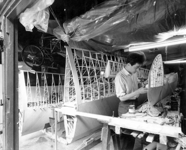
The author building the wings
HELPERS at WOODFORD,ESSEX
I came to adopt a policy of inviting someone to join us only if they could demonstrate an ability to perform at least one relevant task better than anyone else in the group. Susan and I had help with construction from John Bowan, Martin Gelling, David Green, Victor Hurran, Eric Gilbert, Helen Kuczinska, Geoffrey Roper and Jennifer Roper. Victor Hurran, who was a student at the City University, London at the time, was able to make an analysis of the aircraft's flight dynamics, with other students including Dave Newby. This counted as part of their course and they used the college's computer. The result was that a dihedral of 5 degrees was recommended for stability. Alan Vincent, an ex-colleague of mine, gave design advice from a prospective pilot's viewpoint. On one occasion he took Susan and me in a light aircraft to West Malling, one of the airfields we were considering.
1963 REDESIGN FUSELAGE
In January 1963 I redesigned the fuselage. The existing tail components and the propeller were to be modified to suit. I discovered that a propeller, efficient under the flight conditions of the new design, could be made by adding 9 inches (230 mm) to the tip of each blade. The lower part of the old fin became the upper fin on the new configuration. The original ball-race bearing is still there at the top of the fin. At this stage the original tailplane was incorporated, but before flight this was replaced. Tube as bought for the boom was ideal for the pylon structure. I realised that the pitching moment of inertia on an HPA was likely to be considerably smaller than the moments of inertia about the other two axes. In the belief, at the time, that flight-dynamics would be improved if this disparity was minimised I drew Jupiter with a long fuselage. In deciding the wing position relative to the fuselage, there were three considerations :-
In a 5 degree bank, the wheel must be the lowest point.
The lower the wing , the more beneficial ground effect.
Interference drag must be minimised.
( Nowadays, more attention is given to interference drag and less to having a low wing)
INTERFERENCE DRAG
Having heard of the problems SUMPAC had encountered with interference drag at the pylon to wing junction, I gave very careful attention to this area. In our case the top of the canopy would also be above the wing. It was arranged that at no point would the region behind maximum thickness on any two of these components coincide. The base of the pylon has greater chord than has most of its length; not, as it might appear, for structural reasons but so that for the thickness necessary for chain clearance a section of lesser thickness ratio may be employed. The small pod at the top of the pylon could have fulfilled its task of fairing the top of the transmission without protruding forward of the pylon.
However, drawn like that it looked hideous, and a few square inches of area were added for aesthetics. The shape of the front fairing was dictated by my choice of a cyclist attitude pilot, and this was faired in to a glider-style rear fuselage in a functional manner. The point of inflexion of the "S" curve so formed was arranged to coincide with the joint of the fairing. The rear-fuselage was designed with stringers along the sides and top to split the Melinex panels down to a size which would not flap, and to keep the Melinex away from the struts. They would also reduce the effective strut-length of these members. Because of a misunderstanding these stringers were actually assembled inside the struts. The lower fin neatly houses the tailwheel and reduces the torsion applied to the rear-fuselage under rudder loads, by partially balancing the load from the upper fin. It was proportioned so that rear-fuselage torsion resulting from side-load on the tailwheel had the same magnitude as in the rudder-applied case.
VISIT BY PRESIDENT RAeS
Susan had kept us in touch with the RAeSMPAG, and in February 1962 it was arranged that Beverley Shenstone would visit. This was his year as President of the Society. I couldn't believe it. He came. He was impressed. "That looks more like an aeroplane", he said, looking at my drawing board. This despite the fact that the scheme of having the propeller concentric on the fuselage, as originally proposed by him for HPA in 1957 had been abandoned. He saw the the pack of wing-nose-ribs which was declining in height as we took them off the top for assembly to the spars, - indicating progress.
GRANT
We applied for a grant from RAeSMPAG funds for completion of Jupiter, to my 1963 design. We were successful. In total, nine increments of £100 were claimed. On each occasion we had to justify past expenditure. There was minimal delay, because of the system of delegation then in use. Many materials were given free by the manufacturers, and Sir Stuart was providing space, heating and lighting. Wing construction continued during that year.
In 1964 I turned my mind to the details of the transmission, and this and the seat frame were made. There are four rotating parts. The pedals and wheel are concentric, and a chain from the pedals drives the layshaft at a gear-ratio of 2/1. From the layshaft a chain twists up to the propeller shaft and another chain takes the drive back to the wheel. This all worked satisfactorily when a spring-tensioner had been added to the propeller chain. The layshaft was arranged to rotate at double pedal speed in order that a Bradshaw spring could be incorporated.
BRADSHAW SPRING
This is a device to reduce the cyclic variations in torque which occur when anyone pedals anything. A crank on the layshaft is connected to a spring. This spring will be loaded while either of the feet are at the front and will unload, returning its energy, to help carry the feet over the top and bottom of the stroke. On Jupiter the shaft was made to suit the fitting of such a crank, but no arm or spring was ever fitted. Manufacture of some of the transmission components and the brazing of the seat frame were done outside by specialist firms. The rear-fuselage structure was made and by July 1964 we were able to invite Mr Shenstone to witness testing of the transmission system. He sat and pedalled it himself and the propeller spun and rustled the leaves on the trees of Sir Stuart's famous arboretum. Wing construction was complete by the end of 1964.
1965 CONTROLS
I had considered all the possible combinations of pilot-hand-movements to correspond with each of the control-surfaces. It annoyed me that the only logical one was a copy of the Puffin. Already the nose looked like that aeroplane, and I would have liked to show some originality. I rigged the controls so that rudder operation is in the same sense as the steering of a bicycle. Later I learnt that the Hatfield group had followed an aircraft-rudder-bar, which is the opposite way. Another innovation was to make only part of the length of the elevator twist-grip movable. I felt that this would enable more precise control. I couldn't imagine applying aileron and not inadvertently applying elevator without a fixed part of the hand-grip to hold onto.
( In later years, I have observed such an arrangement on bicycle handlebars for the gear-change. I believe that mine was the first.)
Aileron linkage was designed with two options. The first was a simple linkage so that one aileron moved up the same amount as the other moved down (Max. +17 degrees, -17 degrees). The other option was to have one move up and the other not move (+45 degrees, -0 degrees). This would involve restraining springs. John Potter did not like the idea of springs and only the simple system was used. The control bar and some of the control linkage was completed at Woodford, Essex. All the Balsa hoops for the cockpit canopy were made and this was partially assembled. At this time, it seemed evident that Jupiter would fly. It also seemed evident that it was unlikely to fly the Kremer figure-eight circuit since it was similar to others that had not done so. However I was confident that since there were so many "measures" such as altitude, turning ability, duration and rate of climb, that there would be one at which my design would excel, but couldn't then specify which of these. As things turned out, John Potter decided to go for distance, and made a record. The plane was also recognised as having the most accurately made wing-profile. I hadn't seen the other wings and assumed they were being made as accurately as ours.
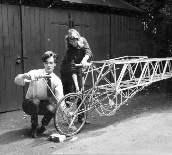
The author and Susan Roper checking the controls of Jupiter
VISITORS
Some visitors to the workshop treated the partly-built aircraft as though it was more fragile than it really was, but sadly that didn't make up for the others! Bitter experience showed that usually there is a complete lack of appreciation of what can be handled and how; in particular, that a half-built component is more vulnerable than it will be when complete. `Friendly' photographers assumed a divine right to anything and were amongst the worst. No malice was involved, and therefore further damage was often done when they tried to `just put the bit back again'. Notices were found to be useless, verbal requests little better. One ruse that was found to work quite well was to realise that they WILL handle something, and to hand them an old testpiece. Another is as follows. In order to help prevent ourselves from blundering into anything that mattered, we had been found it worthwhile to arrange a few inches of scrap wood jutting out from any component so that one only snapped this stick off if passing too close. Use of these sticks provided the clue to the most effective guard against visitor-damage. A few more were added, typically along the span, and it really did work like magic in keeping anyone off. Present someone with a component in its assembly jig, and they would always reach forward and feel it. Fix a few two foot lengths of 1/8th inch square Balsa projecting from it, and although they were perfectly capable of reaching past these spikes, experience showed that they just didn't. Surprisingly, it works. This was my experience in Sir Stuart's garages. It is true that the spike principle is effective in minimising damage both from constructors clumsiness and from outsiders. However it is clear that at best this is only part of the answer to a problem that I failed to solve. Another recommendation, which again is only part of the answer, is to acquire a trailer at an early stage and use it to store any parts not being worked on. You're going to need a trailer eventually anyway.
1966
Another of the mistakes I was making was not to realise to what extent skills other than engineering were needed.
EXPONENTIAL "PROGRESS"
It was around this time that work started to slow down. Half of what remained to be done was being done each year. On this basis it would take forever. The reasons for this were all organisational, not technical :-
NO AIRFIELD
The authorities at various airfields were contacted. In some cases they even said `Yes, bring it here', but the plane was not ready at that time, and we could give no definite date when it would be. In other cases hangar rent was prohibitive. It was realised that a grass field would not be adequate.
NOT ENOUGH PEOPLE
During 1963 and 1964, over half of an aircraft was built with not much more than one person working normal hours. If we count this as equivalent to 1 1/4 people, this implies 10,000 hours total construction time. Figures of the same order were quoted by members of both the Puffin and the Toucan groups. Thus the basis on which the work had been progressing could be said to have been satifactory, if it could have continued. At this rate construction would have been completed during 1966. However, the time involved in making arrangements for a move was not now (1965 onwards) being spent on construction. It was also felt, at the time, that more people, conversant with the project, would be needed during and after any move.
LACK OF FINANCE
From 1963 onwards, Sir Stuart had provided building space, and materials had been donated by firms or bought from the RAeSMPAG grant. Domestically, Susan had been the sole breadwinner, thus supporting me, but this had meant that money available for luxuries amounted to little more than the cover price of "The Observers Book of Astronomy". There was no money or hope of money to cover moving and flying expenses, nor the additional domestic costs this might incur, although we had gone as far as obtaining a small caravan and locating this close to an airfield at which we had been given permission to operate the aircraft. However the airfield circumstances changed, and the caravan was towed back to Woodford, Essex.
MORALE
`Oh, I would never have the patience, I am surprised you have', was a remark often made by someone seeing the amount of work involved. Logically, it can be inferred that the magnitude of the speaker's surprise would have been less if morale had started to drop after two years rather than after three years. But it wasn't so much patience running out as losing a sense of direction. I was motivated to make the spars and ribs because I could see that these would form the wing. I was motivated to make the wing because I could see that this would fit to the fuselage. But there is no incentive to complete the construction unless it can be seen that there are the airfield arrangements ready for the next step - flying. Love blinds, but I have heard Susan described as a very sensible person. Her support, right up to helping arrange the handover demonstrated an exceptional strength of character and level of commitment. But she also, after so many years of the lifestyle we had chosen was feeling and showing the strain. The strain of thinking up answers to `When is it going to fly?', alone would have been too much for many others, over that length of time.
1967 PROGRESS EXPONENTIAL
1968 DISASTERS
1968 was a year of disasters. One of these was that I was injured in an accident. 5th February 1968 was the last day I worked on Jupiter until much later
LOOKING FOR TAKERS
Susan and I realised that the best chance for the aircraft was for someone to take over. She wrote to the RAeS Journal and Flight International and arranged for them to publish "... should anyone wish to save the project will he contact .. S.Hodgess Roper .".
1969
Beverley Shenstone (ex-president RAeS) wrote on 1st January 1969 `... I am very sorry to hear of the difficulties and vicissitudes that you have had to bear... ... It appears to me that what you are doing to enable some other person or group to take over the project is the correct thing to do..' and `..write about your aircraft. Describe the technical design, with reasons for decisions made. Discuss the main problems which arose, both technical and organisational. Point out for the benefit of others, things to avoid and things of positive importance.'
Am doing so.
Various people showed interest until they appreciated that a take-over would involve them taking it away. One group and one individual visited the garage in January, but declined the offer.
FIRE
In June a fire destroyed part of the machine. From this time on, not being so well stored, the remains further deteriorated