
Before 1939
MUSCLE ASSISTED FLIGHTS BEFORE 1939
ICARUS and DAEDALUS
Everyone knows that in the Greek myth, Icarus fell into the sea while trying to fly using wings made of wax and feathers. This myth is often used to support the modern myth that "human powered flight is impossible". What the modern myth-tellers don`t tell you, when quoting the ancient myth is that Daedalus did make it across the sea. Yes, it can be done, and even the very route flown, in the ancient myth by Daedalus, has in recent times been flown, by a Greek cyclist in a plane built in America, named, appropriately Daedalus.
TOWER JUMPERS
Quite a lot of people actually did jump off towers, from around 1100 upto around 1700. The area of their wings was always too small. If they were copying birds, what a shame that they couldn’t see that wing area must be in proportion to weight. Consider the size-range of natural flyers. Insects take off easily, birds not quite so easily and swans - with difficulty. For us humans, we need an enormous wing area, and it is more difficult still.
BLANCHARD'S BALLOON
Reay 1977 writes " Jean-Pierre Blanchard was one of the pioneers of the hot air balloon, (invented in 1783 by the Montgolfier brothers). His most significant contribution to human-powered aeronautics was his use of a propeller, manually rotated, mounted on a balloon. Using this he was able to exert some limited control on the speed and direction of flight."
DEGEN'S BALLOON 1808
Jakob Degen of Vienna appears to have obtained most if not all of his lift from a balloon beneath which he was suspended together with a pair of devices, one on each side of him. These had the appearance of umbrellas but their use was more like parachutes. Once airborne, he had some control of his altitude, by tugging down on a bar connected to the centre of each of these, the perimeter being fixed to a framework. Degen, a ribbon-maker and later a clock-maker, is of interest if only because reports of his performances omitting the fact that a balloon was involved reached Sir George Cayley. Hence Cayley, the inventor of the aeroplane, was encouraged to continue his researches.
THE PEUGEOT PRIZE
In 1912, Robert Peugeot of France offered a prize for the first flight of a distance of 10 metres (33 feet). There were many attempts at this, and Peugeot gave several consolation prizes, some of them for distances less than the long-jump record of the time which was 7.61 metres,(Peter O'Connor in Dublin, 5 Aug 1901), but the prize was not won for nine years. .
An example of an aviette. RAeS collection
POULAIN/FARMAN
A machine was built by the Farman company and pedalled by Gabriel Poulain over the specified distance in both directions early on the morning of 9th July 1921 with Robert Peugeot watching, with a distance of 11.98 metres. (Incidentally, two weeks later, the long-jump record was reset at 7.69 metres by Edwin Gourdin on 23rd July 1921 in Cambridge Massachusetts. ) The Poulain Farman machine was undoubtedly a human-powered-vehicle. It was a biplane with a span of 20 feet (6 m) and a wing-area of 132 square feet,(12.08 m2) (i.e. larger than some wings built for the purpose of true human powered flight in the 1960's). There was a fairing around the person and bicycle. There was no propeller and there were apparently no aerodynamic controls. The total weight was 201 lbs.(91 Kg)
LIFT THEORY
The lifting force, (lift) produced by a wing is mainly a function of the area of the wing(s), the density of the air, the speed of the wing relative to the air and the shape of the wing section. The other factor is the viscosity of the air, (see Reynolds number in Glossary). The section shape and its angle relative to the motion determines the factor Cl or "lift coefficient" in the formula
L = Cl x ro/2 x V2 x S
where L = lift, ro = air density , V = velocity and S = area. Cl is a pure number (dimensionless), hence if one converts to a different system of units its value is unaltered.
In round terms, one might assume that Poulain's wings achieved a lift coefficient of 1. Assuming also the typical sea-level value of air-mass-density of 1/420 in the ft/lb/sec system, and knowing the wing area and the weight that was needed to be lifted, one may state :-
210 = 1 x 1/840 x V2 x 132
which gives V = 36.5 ft/sec or 25 mph
However, to have travelled 11.98 metres (39.3 feet), he would have needed to be moving faster than this when leaving the ground. A rough estimate of this extra necessary speed can be made by assuming a glide-ratio of 5/1, (typical for hang-gliders), that is he could have travelled 39.3 feet forward while losing 39.3/5 = 8 feet in altitude whilst maintaining the same speed. The extra energy needed is the same as that needed to climb this height. The calculation is done most simply by converting the forward speed into its equivalent height using
height = 1/2 x 1/g x V2 = 1/2 x 1/32.2 x 36.5 x 36.5 = 21 ft
Hence total equivalent height is 21 + 8 = 29 ft which is equivalent to a speed of half of 1/g times the square root of 29 = 43 ft/sec (29 mph).
Hence, assuming a lift coefficient of unity this would imply a minimum flying speed of 25 mph, and if we assume a glide-ratio of 5 then Poulain would have needed to achieve 29 mph just before take-off to provide the momentum to carry through the air over the distance. Poulain was a racing cyclist and an experienced pilot. Is it a bike ? is it a plane ? No, it was a machine which had been optimised over nine years purely for the purpose of winning the Peugeot prize, and was demonstrably the appropriate vehicle for the purpose. Poulain and the Farman company succeeded with this simple layout against a competition of machines with flapping wings and propellers, some of them being tricycles or having other appendages adding to the weight and drag. There is no record of anyone else operating this machine, or of whether it was stable or whether Poulain personally had gradually to acquire the specific knack of controlling it. Clearly, without some sort of drive when airborne, one will not get very much further than this, but note that all those of the early aircraft which intended unaided take-off, and some of the later ones, used drive to the ground-wheel as well as to the propeller.
LIPPISCH 1929
Dr Alexander Lippisch, a prolific designer of sailplanes and other aircraft, built an ornithopter (see Glossary) in 1929. This was always launched like a glider (Lippisch 1960). The principle Lippisch used relied on the wings twisting during the flapping cycle. In general, on an aircraft the centre of pressure of the lift will not remain on the axis of the spar during flight. This offset loading will tend to warp the wing. On almost every other aeroplane this is a problem which must be overcome, usually by making the wing structure stiff enough to resist this torsion. But on this aeroplane, Lippisch tried to make use of this effect; the extra, and different, forces on the wing during the downstroke would hopefully warp it more. Hence, the effect of the wing flapping would propel the plane on a similar principle as a fish's tail propels a fish.
However, for one reason or another it did not work. Perhaps the wing was too torsionally stiff - again the opposite of what is unfortunately more common. Lippisch added flexible extensions behind the trailing edge and it was then found that flapping of the wings slightly prolonged the flights, but he could not understand the still disappointing results until he realised that the pilot, Hans Werner Krause, was not really pulling very hard, and didn't see the point of it. He then offered to pay Krause's rail fare to see his girl friend for the weekend, if he were to fly from the usual launch point over a specified puddle about 300 yards away. The course was covered on the first attempt.
MUSKELFLUG INSTITUT (Institute of Muscle-Powered-Flight)
This was set up in 1935, within the Gesellschaft Polytechnic, Frankfurt. Oskar Ursinus, director saw as the prime question the determination of power available (from a a person`s muscles). A prize was offered for the first flight in Germany over a 1 km course. The data from his tests on muscle-power were made available to designers in 1936. Unfortunately no further research could be carried out by the Institute because of the onset of war.
MUFLI
This was the only relatively successful contender for the prize offered by the Muskelflug-Institut. Helmut Haessler finalised his design in 1935. His estimate of the available power was too high. Eventually, since the results of the tests from the Institut were not published he and a colleague Franz Villinger performed their own tests on human-power by having one cyclist tow another who read a spring balance on the handlebars attached to the tow-line. " It was not realised until our own tests and those of the Muscle Flight Institute, which was founded later, had been done, that the earlier data gave more than double the actual power." (Villinger 1960) None of these human-power data mention the weight of the person producing it. Franz Villinger and Helmut Haessler were both experienced in aircraft through their employment at Junkers. The neatness of the configuration and the similarity to a sailplane conceal some subtle points. The length of the drive is very short and the propeller-support-pylon and wing do not interfere aerodynamically as they do on some later machines. (See below re Interference Drag). The frontal area is desirably low, although this meant that it was most awkward for the pilot to get into or out of the Mufli.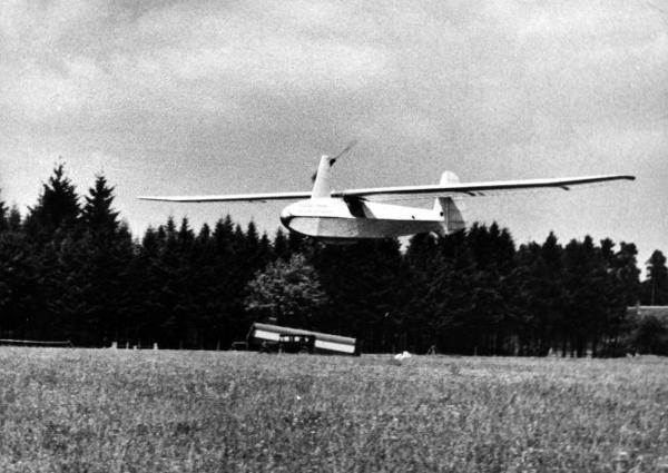
Mufli flying in 1935. RAeS collection
TOTAL ENERGY COST OF POWER TRANSMISSION SYSTEM
Haesller argues that the effective total drive efficiency is high (Haesller 1961). To calculate the total energy "cost", he summates four items. Namely,
the weight of the drive mechanism,
the weight of its supporting structure,
power losses in the drive,
power losses in the propeller.
According to his argument, if one assumes that the pylon would have been there anyway to act as king-post (Glossary), which it might have been, and that the drive mechanism was very efficient, which it probably was not, then this analysis shows the Mufli system to be a good design compared with others. Such an analysis does not really go far enough however, as he does not consider the aerodynamic effects, i.e. the drag of the pylon (see SUMPAC and Jupiter). On some designs, e.g. Puffin, Linnet, the drive-train greatly constrains the fuselage design, hence the relative advantage of the Mufli layout could be even more than Haessler claims. Professor Hidemasa Kimura, of Nihon University writing about their Linnet wrote (1977) "The basic form of the Linnet series embodied the original beauty which was unparalled. What was wrong [with the Linnet] was that a torque shaft measuring about four meters long was needed to transmit the power of the pilot from the pedal to the propeller because the propeller was located at the tail end. The vibration of the shaft, which was witnessed in the initial phase of the program, was solved by increasing its outer diameter. The shaft, however, could not be elongated beyond reasonable limits. This made it impossible to elongate the moment arm of the tail. [The tail volume ratio of the horizontal tail was 0.305 for the I model and 0.334 for the II model.] Such structural deficiency brought on insufficient longitudinal stability, which caused the pilot constantly to pay his exclusive attention to the maintenance of longitudinal trim. It was not easy to attend to the delicate manouvering of the airplane while pedalling with both feet at full power simultaneously. There were many cases in which the airplane prematurely hit the ground as a result of a loss of foot power caused by excessive attention to piloting. The pilots for the past series of manpowered flights were chosen from among students who held private pilot licenses for airplanes or gliders." Here Kimura is showing how much the drive-train is dictating. Also he is pointing out the benefit of a stable aeroplane to reduce the pilot's work. See Gossamer Condor and Chrysalis, and Bryan Allen's comments on these two, having flown both.
LONGITUDINAL (PITCH) CONTROL & STABILITY
( See foregoing paragraphs, sections on Puffin, Jupiter, Wright, and "longitudinal" in glossary.) As originally built, both wing panels of the Mufli twisted and the tailplane stayed fixed. This proved over-sensitive and pitch behaviour was such that a conventional moving elevator was built for later flights. Lateral control (see Glossary) was by both entire wing-panels moving. With two bracing wires beneath the wing, this needed only a simple mechanism. There are no reports of turns, but the aircraft made 120 flights, hence one assumes lateral control was effective enough for straight flights. Construction was of spruce and cedar as used for aircraft of that time, and the aerofoil section was Gottingen 535, a highly cambered section intended for gliders, which is aimed at producing high lift, but not at extensive laminar flow. The drive belt was cloth which needed frequent tightening. The first officially recorded flight of the Mufli was at 11.10 am on 29th August 1935 in Frankfurt with Herr Duennebeil as pilot, but the author heard Villinger in London in the 1960s say that the first flights had been made by him and Haessler. The longest recorded flight was on the 4th July 1937. This was 779 yards, and for this the Institut gave a consolation prize. Villinger wrote in 1961 that this had been achieved in "near ideal conditions" (Villinger 1961). This aircraft was to influence British theorists and designers in the 1950s and 1960s. Compare the propeller positions and general glider-type layouts. It was the only HPA known to have flown. All the Mufli take-offs were by bungee, as intended. ( See HVS for a Villinger design forty-eight years later.)
HANS SEEHASE
This man built an aircraft for the same competition. There is no record of this plane having taken off. However it is of interest because of many of its design features. The wing structure was aluminium alloy tube with widely spaced ribs and an all fabric covering, in order to reduce weight even at the expense of increased drag. This principle was ignored by other designers for 42 years, perhaps because the plane was deficient in other ways, notably a clearly inefficient propeller. Perhaps if the Seehase design had been sound all over and it had flown, then others might have adopted a hang-glider type of wing earlier than the Condor. The principle of the transmission system has never been used on any other project. Chain from the pedals drove a layshaft (intermediate shaft). This had two cranks on it as if it were the crankshaft of a two-cylinder motor-car. The con-rods did not go to pistons, but to another similar crankshaft. This second crankshaft is the propeller shaft, which as usual was at right angles to the layshaft. Theoretically it doesn't work, because the con-rods have to change length during the cycle. Seehase made it work on the ground by incorporating rubber buffers, as did Wilson later (see below). Gearing in the chain drive to the layshaft can be readily adjusted.
PEDALIANTE
Enea Bossi, an Italian aircraft designer, started his research into HPF in the 1930s by fitting a propeller onto a tricycle. This proved to be an unstable vehicle and he erroneously believed that an HPF with only one propeller would also be unstable, hence his choice of wing-mounted contra-rotating propellers with the accompanying complicated drive. The Pedaliante was of conventional glider configuration and construction, and with a span of 58 ft (17.7 m), area of 250 square feet (23.2 m2) and weight of 220 lbs (100 Kg). It is generally agreed that this aircraft made many dozen flights after towed launches. There has been much dispute as to whether it ever took off under the pedal-power of the pilot alone. There is no record of official observation of it having done so. If it did, it would of course have been a world-first, preceding SUMPAC by thirty-five years. Some of the arguments for and against the validity of Bossi's claim to have done so are presented by Sherwin (1976). In the period from 1958 to November 1961, one knew that the Pedaliante "might have done", and this mirrored most people's expectations about whether their own projects would ever work, or indeed whether HPF would ever be possible. Yes it's true, we really did say "Yes, but will it fly ? ". Neither of these pre-war aircraft had ailerons, yet all the early British HPA used such devices to attempt to get lateral control

Pedalianti during construction. RAeS collection